Basic electrical principles explained - Part 2
This page will teach you the fundamental basics of how electricity works. It will help you to understand how resistance plays an important role in almost every electrical device ever made.
Resistance
Now we have familiarised ourselves with Volts, Amps and Wattage, we can take a look at resistance in electrical circuits. Resistance is a point in a circuit where current is forced to slow down. How much it is slowed down will depend on how much resistance is placed into the circuit. When electricity flows across a resistance, some of its energy will be converted into a different form. For example, an incandescent light bulb is a form of resistor, where the energy travelling across it is turned into heat and light.

With some creative designs, resistors can be made to perform some very useful tasks. The heating element found in kettles, irons, fan heaters and in fact any electrical heater are simple resistors. These types of resistors are made from thick wire that can withstand high temperatures. For heating elements submerged in water, the wire is covered in a ceramic coat and sheathed in a metal jacket. Elements used to heat air are usually exposed without any additional layers, except the appliance casing which protects you from burns or electric shock.
Small resistors are also used extensively in electronics. The small, circuit board mounted cylinders are not there to create heat, but rather limit current or voltage in order to make another component behave in a certain way. On circuit boards, resistors are often used to create a different voltage from that of the supply. They also find some use as current limiters.
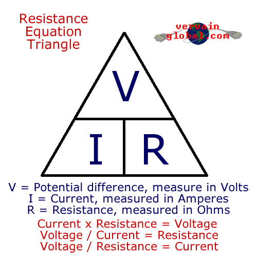
Resistance is measured in Ohms, and the resistance equation triangle works just like the power triangle we looked at in the first article. The symbol for resistance is the Greek Omega sign ( Ω ). Using the formula from the resistance equation triangle, if you measured a voltage of 12v across a light bulb, and it was drawing 0.8 amps, its resistance would equal 15 Ohms. 12 / 0.8 = 15. One of the most important behaviours of resistors are the voltage drop they create across them. This attribute is widely used in electronics.

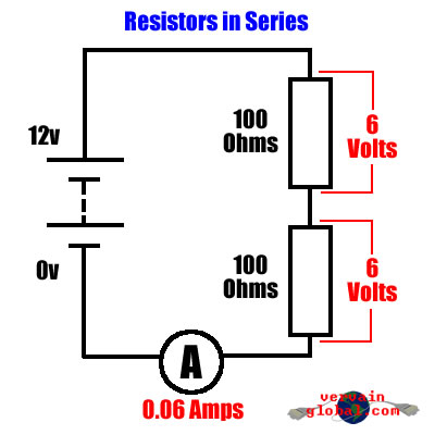
If we were to wire two resistors together in series (that's one connected to the other at one end only), and wired the spare ends to a battery, a current would flow through both and create a circuit. Remember, that when two or more resistors are connected in series, their resistances add together. If you have two 100 ohm resistors wired in series, the total resistance will actually be 200 ohms. Let's say the battery provides us with 12 volts, and both resistors have a value of 100 Ohms. The voltage across BOTH will be 12 volts, but if you were to take a volt meter and measure across just ONE of the two resistors, the reading would be quite different. In this case, you would get a reading of 6 volts.
Having two resistors wired in series will also change the amount of current that can flow across them. Because the two 100 ohm resistors work to create an actual resistance of 200 ohms, the amount of current flowing through them will be halved. If you were to add another 100 ohm resistor in series with the first two, the current flowing would be reduced to a third, and the voltage across each would drop to 4 volts. This effect is often used in electronics to provide a lower voltage to a sensitive component.

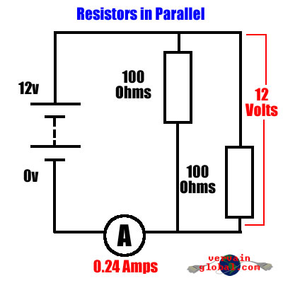
Now let's change the wiring so that the two resistors are now in parallel. That is, both ends of each resistor are connected together, and the battery wired across those paired ends. Now, because each resistor is connected directly to both ends of the battery, the full 12 volts will be dissapated across them. The total resistance is now quite different. Because they are handling the full voltage together, instead of sharing it between them, more current will be allowed to flow. In the case of our 100 ohm resistors, the total combined resistance in parallel will be 50 ohms, and the current flowing will be 0.24 amps. Each resistor will be allowing 0.12 amps to pass.
Working out the total resistance of several parallel resistors is a bit more tricky. One thing to remember is that the total resistance will always be less than the smallest resistor in parallel. The formula is R=1/(1/R1)+(1/R2)+(1/R3). Agreed, that's pretty confusing. To break that down, for each resistor you should start with the number "1" and then divide it by the resistance of your resistor in ohms. Do that for each resistor you have in parallel. Then add these values together. Then, take the number "1" and divide it by your total number from adding the values together and you will have your total resistance. For our two 100 ohm resistors we would do: 1/100=0.01 for resistor one. Then: 1/100=0.01 for resistor two. Add those together and you get 0.02. Now we need to do: 1/0.02=50 ohms. Have a go on your calculator until you are familiar with the formula. This formula can be scaled up to include as many resistors in parallel as you need.
Resistors in parallel are not seen very much in small electronics. More often, a setup like this will be used to dissipate unwanted power. Long time remote control car enthusiasts may be familiar with this idea, as it was important to fully dischange old style Ni-Cd batteries before recharging them, and often a strip of high wattage light bulbs was used to do this.
So now you know a little bit about electricity and how it behaves. Don't worry if you haven't understood everything right away. If you'd like to learn more about electricity and electronics, pop down to your local library, or have a search on the web. There are many comprehensive guides available. Have fun, and above all, stay safe.
