Make Your Own Remote Shutter Control for Android and iPhone
Just about every modern smartphone comes equipped with a high quality camera, and many phones even come packed with quite a few professional features you'd have only found on expensive DSLR's a few years back. One feature I've always wanted is a remote shutter function. Although cheap and nasty Bluetooth buttons can be found for less than £10 on the big marketplaces, I took a little inspiration from the old selfie sticks that were so common in the early 2010's and decided to make my own high quality, wired remote shutter cable.
Introduction

On almost all modern smartphones, it's possible to trigger the shutter button using controls normally found on a wired headset. With iPhone and Android devices, the "volume up" and sometimes (not always) the "volume down" buttons can be used to trigger the shutter. This usually works on the handset volume buttons, as well as wired and wireless headphone sets.
Smartphones with a 3.5mm headphone jack are capable of this too. Essentially, using analogue signals, it is possible to trigger the camera shutter via this port.
This feature makes it easy for us to create a remote shutter control cable that's far longer than the lead on a typical headphone set. This is useful for taking shots where you need to position your phone out of reach. An example might be taking a picture of a large group of people with nobody having to miss out on being in the picture, or taking adventurous selfies that need the phone to be a little further away. Other applications could include taking shots in low light, where keeping the device perfectly still is important, or using further circuitry to trigger the camera on a given event.
What You'll Need
The basic circuit is made up of a few simple components. They are easy to find in an electronics store, or an online retailer. They can even be salvaged from a broken set of headphones or other audio devices. The parts needed are:
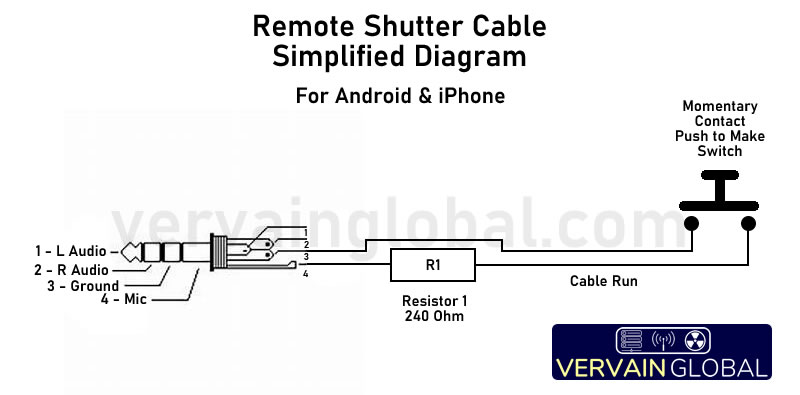
- A 3.5mm, 4 pole jack. This connects to the wired headphone socket.
- 2 core cable, length as required. You could use doorbell cable, speaker cable etc.
- A momentary "push to make" button. Avoid using toggle switches unless you intend to take long burst shots.
- A 240 Ohm resistor. This can be a small quarter watt version, just make sure its tolerance is within 1% to avoid unpredictable responses from your phone.
- Heat shrink or insulation tape, to protect exposed terminals and neaten up connections.
- Preferably a soldering iron, solder and wire cutters. Some components may use screw down terminals, but this is rare.
Assembly
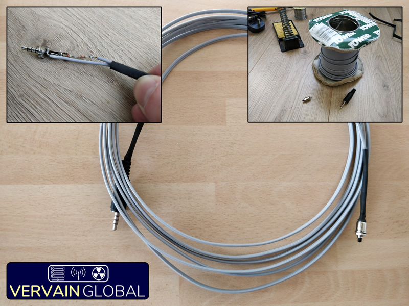
Once you have your components, it's time to put it all together. Start by deciding the length of cable you'll need. The cable should be long enough to meet your needs, but avoid making it any longer than necessary. Beware that making the cable excessively long may prevent it from working correctly, as the resistance may be increased beyond the acceptable tolerance. A very long cable may also pick up a lot of electromagnetic interference (EMI), which your phone may interpret as a signal to change the volume or play/pause a song. If you're intending to make a very long cable, you may wish to consider using a shielded cable to help prevent this. In my design, I used 5 meters of speaker cable.
If you're using heat shrink to cover the ends (I recommend this, it'll look much more professional), now is the time to thread it onto the cable. Cut two pieces of heat shrink at lengths of around 2 inches and slide them onto the cable. Make sure they don't slip off before you have soldered both ends together! Don't forget to also slide the back part of the 3.5mm jack over the cable too.
Next, strip back both cores on one end of the cable, and tin the exposed copper. Trim the ends so only about 5mm of wire is exposed, and carefully solder them onto the terminals of your momentary contact switch. If the terminals are very small or close together, it may be worth adding a small piece of heat shrink to just one of the cores before soldering it, and shrinking it over the terminal once you've finished making the solder joint.

Now you can solder your resistor to either pins 3 or 4 of your jack. Make sure you've correctly identified the pins on the back side of the jack. Trimming the leads of the resistor may help fit it entirely inside the housing of the jack, making the cable stronger and more durable. In my case, I didn't have a 240 ohm resistor handy, so instead used two 120 ohm resistors in series. So long as the resistance is within a 1% tolerance, it should work correctly. You can learn more about resistance in our Electrical Basics Article.
Now take the other end of your cable and cut back one of the cores. Tin the end, and solder it to the other pin that you didn't connect the resistor to. Once you've done this, you can cut back the second core so it slightly overlaps the remaining lead of the resistor. Strip back the insulation and solder it to the resistor.
Before applying the heat shrink, it may be wise to test your cable first! Plug the jack into your phone, open the camera app and try pressing the button on the far end of the cable. If your phone took a picture, your circuit is working! If not, you may need to troubleshoot the joints and resistor value. Make sure you've connected the cable to the right pins on your jack, and that your button only completes the circuit when you press it. A continuity meter will be very useful for testing should you encounter any issues.
Once everything is working, you can remove the jack and use a heat gun to shrink your heat shrink down onto the exposed joints. If you're using electrical tape, carefully wrap the joints up, making sure to position tape between the two conductors at both ends. Finally, slide the jack cover down and fasten it to the body of the jack. Most are a screw on type, but yours may vary.
That's it! This simple but very useful circuit will undoubtedly come in handy for those tricky photos that would normally need an extra pair of hands. I've found this particularly useful for taking longer distance selfies without having to entrust a stranger with my phone. It's also great for taking long exposure shots at night, where you need to keep the device very still in order to prevent motion blur.
Taking it Further
This very simple circuit can be easily modified to other uses with a few minor changes. The momentary push switch can be swapped for other trigger components, such as a relay or a reed switch. So long as your phone sees the resistance momentarily appear across the mic and ground contacts, it'll take a picture or begin filming a video. Here are some brief examples of how this circuit could be modified to perform other useful functions.
Time lapse photos. By replacing the momentary button with a small relay, you could enable any type of circuit to provide frequent, regular pulses that will trigger your phones camera. A simple circuit could be used to take a shot every 5 seconds, and the resulting pictures used for a time lapse video of a scene or landscape. Such a circuit could be built relatively simply with a 555 timer and a few other components to regulate the frequency and duration of shutter presses.
Security Camera. Replacing the button with a microswitch or reed switch would easily allow the circuit to send a shutter signal when a door or window is opened. By mounting the switch above a closed door so that it is triggered upon the door opening, you could start a device recording video or it could capture a photo of the person entering. This would work best with an old phone that you don't need to use. Keep the phone plugged into a charger, turn the screen lock off and leave it with the camera app open. Such a design could capture images of an intruder entering a room easily. The files would be available on the phone, complete with time and date stamps!
Published 2nd February 2021.
