Build Your Own Telephone Line Wiretap / Bug
Want to listen in on your home landline 24/7? Here is an easy and cheap circuit that anybody with some basic electrical skills can build in a short space of time. Plug one end into your phone line and the other into a tape recorder and presto! Not a word will go unheard - 04th December 2015
Getting started
This simple circuit will behave as a filter to extract the voice signals from your landline and output something suitable for a tape recorder or anything that can accept a microphone / phono level input. It will filter out the high voltages on the line and set the output audio signal at an appropriate level for your recording device. This circuit behaves as a parallel tap, meaning it does not necessarily have to be wired in between the phone line and the telephone. It can be connected anywhere on the line, no matter how near or far it is from the telephone you wish to listen in to.
For this project you'll need to gather a few small components. These can generally be pulled out of most old appliances or bought dirt cheap at your local electronics or hardware store. You'll also need a small strip of something like Veroboard to build it on, or alternatively if you want to make a more temporary version it could simply be built on prototype board or Breadboard. Using something like Breadboard will save you the job of having to solder parts together if that isn't your thing. You'll finally need to get ahold of a suitable connector for the tape recorder you'll be using (likely a 3.5mm mono jack), as well as a plug for your phone socket (unless you plan to wire it directly into the back of the socket). Typically in the US, an RJ11 plug is used where as the UK has its unique 431A plug. The box below lists the components needed.
-2x 0.1µF ceramic capacitors (Usually marked with the number 104)-
-2x diodes (almost any type of SIGNAL diode will be fine)-
-1x PCB mount potentiometer of around 5k resistance, with logarithmic track-
-Plugs for your tape recorder and phone line socket-
-Prototype board or Veroboard etc-

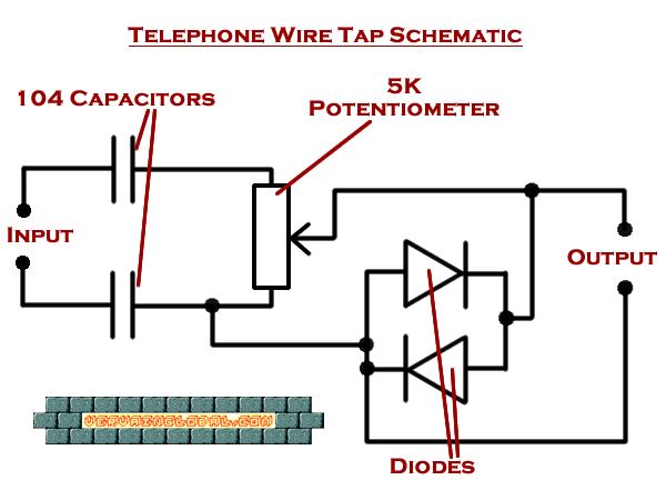
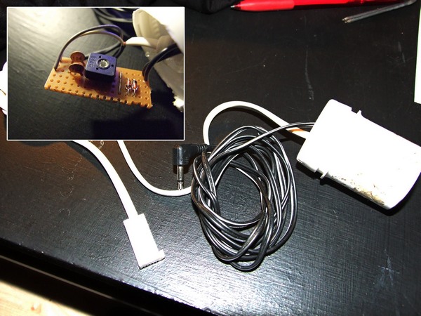
Once you have all the parts and components, you can begin to solder them onto a board, or if you are taking the solderless option, begin poking the legs into the Breadboard so that everything matches the circuit shown in the image to the right. Connect your telephone plug and wire to the "input" side and your tape recorder jack to the "output" side. You may also want to place the completed circuit inside an enclosure to keep it safe and hide it away. I popped mine into a small pill can, leaving the two cables poking out the top.
Setting up

Okay, so once you have finished assembling your circuit, we need to give it a quick test and set the microphone input level. So first let's plug it all in. You can set your recording device to run continuously, but a far better option would be to make use of its VOX function. Not all recorders have this, but most do. This function will only start the recorder when it "hears" a sound, in this case from our telephone line, so it only captures the periods when someone is actually using the phone. Once this is done, pick the phone up and listen for the dial tone. This sound should be sufficient to start your recorder. If it doesn't, you might need to adjust your potentiometer a bit. Turn it until it starts the recorder running. If you don't have a VOX function on your device, you'll just need to record for a bit while lifting the telephone off hook and then play it back. Once you are satisfied, listen carefully to the played back recording. Does it sound clear? Is it too quiet? Is it distorted? If the recording is too quiet, you'll need to turn your potentiometer up a bit. If its distorted, turn it down a bit. It will take a bit of time to find the right level, but eventually you'll find a happy medium. Once you've done this, it is time to stash everything away from sight and set your recording device up to capture conversations.
How it works
Although the circuit is fairly simple, it performs several important functions that prevent the malfunctioning of the telephone line as well as protecting your recording device. A standard telephone line, when not in use, carries a Direct Current (DC) voltage of around 48 volts. When a user picks up their telephone, the line voltage falls to about 5 volts. Passing either of these voltages into your recording device would likely fry the delicate circuits inside. Thankfully, we can use the two small capacitors to combat this. It just turns out that capacitors are great at blocking the flow of DC current when you place them into the circuit in series, while passing an Alternating Current (AC) like the voice audio signal and the ringer pulse. Next up the signal is passed through the potentiometer. This component behaves much like a variable resistor, and will allow us to set how much of the voice signal passes through to our recording device.
After this our signal is almost ready, but we still have to deal with the ringer pulse. This beastly AC pulse normally spikes around the 100 volt area. As it behaves like an AC current, it can escape past the capacitors and into the output side. This is where our diodes come in. They open up to pass any voltage over about 0.7 volts, thus allowing the high voltage ringing pulse to pass through them and safely back to the telephone line ground, while leaving the tiny voice signal free to continue through the output side. They also filter out any unexpected surges or spikes that make it through. Finally, after all this filtering, we are left with the fragile weak voice signal that can now pass to the microphone input of our recorder.
Finally, its important to note that in most countries, listening in on a phone line is illegal unless you inform all parties using the phone (that includes the person on the other end). This article has been written for informational and research purposes only, and the author nor vervainglobal can accept any responsibility for damage, injury or a breach of law that may result from following the advice seen here.
